Home/Blog/Hydrant Engineering: The P.U.M.P. Protocol for Industrial Fire Protection in J&K
Hydraulic Engineering & Pump Skids⏱ 9 min read📅 September 10, 2026
Hydrant Engineering: The P.U.M.P. Protocol for Industrial Fire Protection in J&K
Master the definitive P.U.M.P. engineering protocol for industrial fire hydrant networks and pump rooms: Pressure balancing, Uninterrupted suction geometry, Mechanical tripartite redundancy, and Periodic churn testing across J&K manufacturing corridors.
Author: BSS Fire Engineering Team•Region: Jammu & Kashmir
⚡
Key Technical Takeaways
✓The P.U.M.P. protocol establishes four non-negotiable engineering disciplines: Pressure dynamics, Uninterrupted water reserves, Mechanical redundancy, and Periodic churn verification.
✓NBC 2016 Part 4 and IS 13039 mandate a minimum dynamic residual pressure of 3.5 to 7.0 Bar at the hydraulically remotest landing valve with two concurrent streams in operation.
✓Closed-loop ring mains reduce fluid velocity to <= 2.5 m/s and eliminate dead-end stagnation, cutting frictional head loss by up to 75% compared to tree networks.
✓Pump suction must be positive flooded with eccentric flat-top-down reducers and anti-vortex plates to completely prevent cavitation air pockets and impeller erosion.
✓Statutory pump room skids require tripartite redundancy: primary electric motor pump (2280/2850 LPM), 100% standby diesel engine with independent 24V starter batteries, and an automatic vertical multistage jockey pump.
✓Weekly automatic churn runs (10 min electric, 30 min diesel) with closed discharge valves and circulation bypass lines are mandatory under IS 15301 to prevent shaft seizure and seal failure.
The P.U.M.P. Protocol for Industrial Hydrant Networks
Four non-negotiable hydraulic engineering disciplines mandated by IS 15301, IS 13039, and NBC 2016 Part 4.
NBC 2016 Part 4 Table 7
PILLAR [P]Standard: IS 13039:2014 & NBC 2016 Part 4 Table 7
PRESSURE REGIMES & DYNAMIC HEAD
Residual Head Balancing & Surge Damping across Extended Industrial Rings
Min. Residual Head
3.5 to 7.0 Bar
Simultaneous Streams
2 to 4 Outlets
Peak Ring Velocity
≤ 2.5 m/sec
⚙️Mandatory Engineering Directive
Design closed-loop ring mains (Class C Heavy ERW or seamless pipes per IS 1239 / IS 3589) with hydraulic balancing calculations. Ensure that when two 63mm landing valves discharge simultaneously at the hydraulically most disadvantaged point, residual running pressure never drops below 3.5 Bar (35 meters head). Install automatic kinetic air release valves at high points and pilot-operated pressure relief valves (PRV) on discharge manifolds to arrest transient hydraulic hammer shocks.
🔬Hydraulic Physics & Reasoning
Static head loss increases directly with piping friction (Hazen-Williams formula C=120) and vertical riser elevation. A dead-end tree network experiences catastrophic pressure drops during concurrent demand; a closed perimeter loop divides fluid flow into two parallel paths, halving local velocity and cutting frictional head loss by up to 75%.
⚠️Fatal Field Execution Mistake
Installing concentric reducers on pump discharge lines or omitting surge air vessels. When pumps trip during emergency shutoff, columns of moving water recoil into valve discs, creating extreme pressure wave spikes (water hammer) that shatter cast iron fittings and shear flanged joints.
Field Commissioning & Inspection Checklist:
✓Simultaneous two-stream pitot gauge flow test at remote yard hydrant
✓Dynamic pressure verification at top floor wet riser landing valve
✓Calibration of hydraulic pressure relief valve bypass line to drain
✓Air release valve inspection at all vertical riser summits
Need turnkey hydraulic calculations, pump skid fabrication, or NBC 2016 Fire NOC approval in J&K?
1. The Hydraulic Threat: Why Extinguishers Fail Against High-Thermal Industrial Loads
When an industrial fire ignites inside a pharmaceutical chemical warehouse, packaging store, or manufacturing plant in Bari Brahmana, Samba IGC, or Kathua, the rate of heat release accelerates exponentially within minutes. While portable fire extinguishers provide indispensable first-aid knockdown for incipient blazes under 1 square meter, their discharge duration is physically constrained to 15 to 20 seconds with a total extinguishing agent mass of 4kg to 9kg.
Once flames breach combustible packaging stacks, solvent drums, or structural timber, radiant heat fluxes exceed 25 kW/m²—a threshold where structural steel weakens, roof trusses collapse, and human approach becomes physically impossible. Suppressing an established structural or industrial fire demands continuous, high-volume water application capable of absorbing massive heat loads (water absorbs 2,260 kJ/kg during vaporization).
An engineered fire hydrant system is an industrial facility's primary heavy artillery against catastrophic structural loss. Operating under National Building Code (NBC 2016 Part 4) and Indian Standard IS 13039, a certified hydrant network guarantees that high-pressure water (minimum 2,280 to 2,850 liters per minute) can be deployed instantaneously at any coordinate across the site envelope, long before municipal fire tenders can navigate highway corridors.
Statutory Fire NOC Mandate in Jammu & Kashmir
Under J&K Fire Services regulations and NBC 2016 Part 4, commercial buildings exceeding 15 meters in height and industrial manufacturing sheds exceeding statutory built-up area thresholds are legally prohibited from operating without a fully commissioned, pressurized wet riser and hydrant network connected to an approved static water reserve.
2. The P.U.M.P. Framework: 4 Core Hydraulic Disciplines
Over two decades of on-site fire protection engineering across Jammu & Kashmir reveals a consistent, troubling pattern: facilities invest lakhs into heavy piping and pump hardware, only to experience hydraulic failure during a real crisis or routine Fire NOC audit.
Common points of failure include: water pressure collapsing at upper floor risers, pumps vapor-locking due to air pockets in suction lines, diesel engines failing to start during electrical outages, or dormant pump shafts seizing after months of neglect.
To eliminate these catastrophic vulnerabilities, BSS Fire engineers all industrial fire fighting installations around the rigorous P.U.M.P. Protocol:
P3.5 to 7.0 Bar Residual Calibration
Pressure Regimes & Dynamic Head
Closed-loop ring main sizing, Hazen-Williams friction head calculations, dynamic residual pressure balancing at the remotest landing valve, and surge relief dampers.
UCavitation-Proof Flooded Suction
Uninterrupted Water Reserves
Dedicated static water reservoir sizing (100k–300k+ Liters), split-compartment maintenance design, positive suction geometry, anti-vortex plates, and eccentric reducers.
MTripartite Pump Room Architecture
Mechanical Redundancy Skid
Primary electric motor pump + 100% standby compression-ignition diesel engine + vertical multistage jockey pump with staggered fail-safe pressure switches.
PWeekly Runs & Hydrostatic Proofing
Periodic Churn & Flow Proving
Automated weekly churn testing with volute circulation bypass lines, quarterly hydrant ring flushing, annual 150% flow proving, and Form B compliance certification.
A fire hydrant system is not simply pipework filled with water; it is a precision-balanced pressurized hydraulic delivery network. Under IS 13039:2014 and NBC 2016 Part 4 Table 7, a hydrant network must deliver water at a minimum running dynamic pressure of 3.5 Bar (35 meters of head) at the hydraulically most remote and disadvantaged landing valve, while supporting at least two simultaneous 63mm fire hose streams discharging between 900 and 1,800 LPM.
Maximum pressure at any landing valve must not exceed 7.0 Bar. Pressures exceeding 7.0 Bar subject fire response crews to uncontrollable nozzle reaction forces (recoil), risking personal injury and loss of stream direction. In multi-story buildings exceeding 45 meters, pressure-reducing landing valves (PRVs) or orifice restrictor plates are mandatory on lower levels to step down static riser pressures.
Piping layout geometry is the defining factor in pressure retention. BSS Fire mandates closed-loop ring mains encircling the facility perimeter using heavy-class ERW or seamless pipes (IS 1239 Class C Heavy or IS 3589). Dead-end tree piping networks suffer severe frictional head losses because all water flows through a single conduit. A closed perimeter ring allows water to travel via two parallel paths to any flowing hydrant, reducing local velocity to <= 2.5 m/s and cutting friction loss by up to 75%.
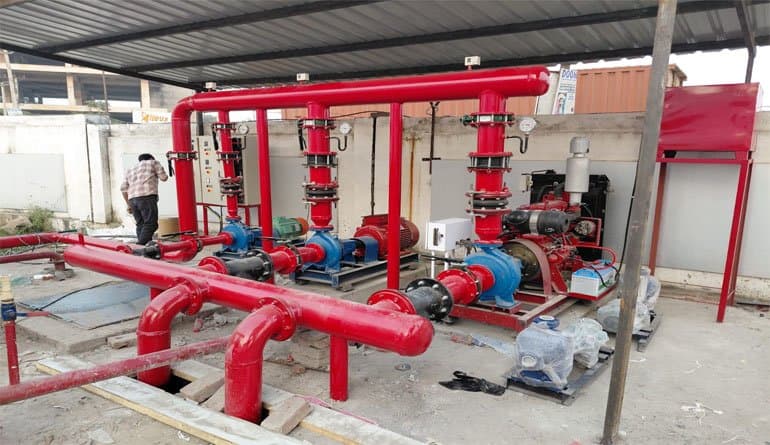
VERIFIED BSS INSTALLATION
BSS Fire engineered industrial pump house installation in J&K featuring horizontal split-case pumps, automatic pressure switch manifolds, and vibration isolation mounts.IS 2190 Standard Protocol
Water Hammer & Surge Damping Engineering
When high-capacity landing valves or pump discharge valves slam shut, the sudden deceleration of moving water produces shockwaves known as water hammer, with pressure spikes reaching 3 to 5 times operating limits. BSS Fire skids integrate automatic pilot-operated hydraulic surge relief valves and nitrogen-charged air cushion vessels to absorb transient shockwaves and protect pipeline integrity.
Fire fighting pumps do not suck water out of a tank; atmospheric pressure and the static liquid column push water into the pump suction eye. If suction pipework is improperly configured, pumps suffer from cavitation—a destructive phenomenon where local static pressure drops below water vapor pressure, forming microscopic vapor bubbles that implode violently against the bronze impeller, causing deep metal erosion, intense vibration, and total loss of discharge volume.
Under IS 15301 Clause 5, positive flooded suction is mandatory for all primary fire pumps: the centerline of the pump suction nozzle must sit below the minimum effective water level of the static storage tank. Suction lift setups with foot valves are strictly prohibited for industrial occupancies due to the danger of lost priming.
To prevent cavitation and air entrainment, BSS Fire enforces two critical geometric standards on all pump skids: First, suction reducers must be ECCENTRIC with the flat side positioned on top (flat-top-down). Concentric reducers trap pocketed air along the upper pipe wall, which gets drawn into the impeller throat. Second, suction inlets inside the water reservoir must feature anti-vortex baffle plates (IS 15301 Annex B) to prevent the high-velocity intake from creating surface whirlpools that suck atmospheric air into the pump.
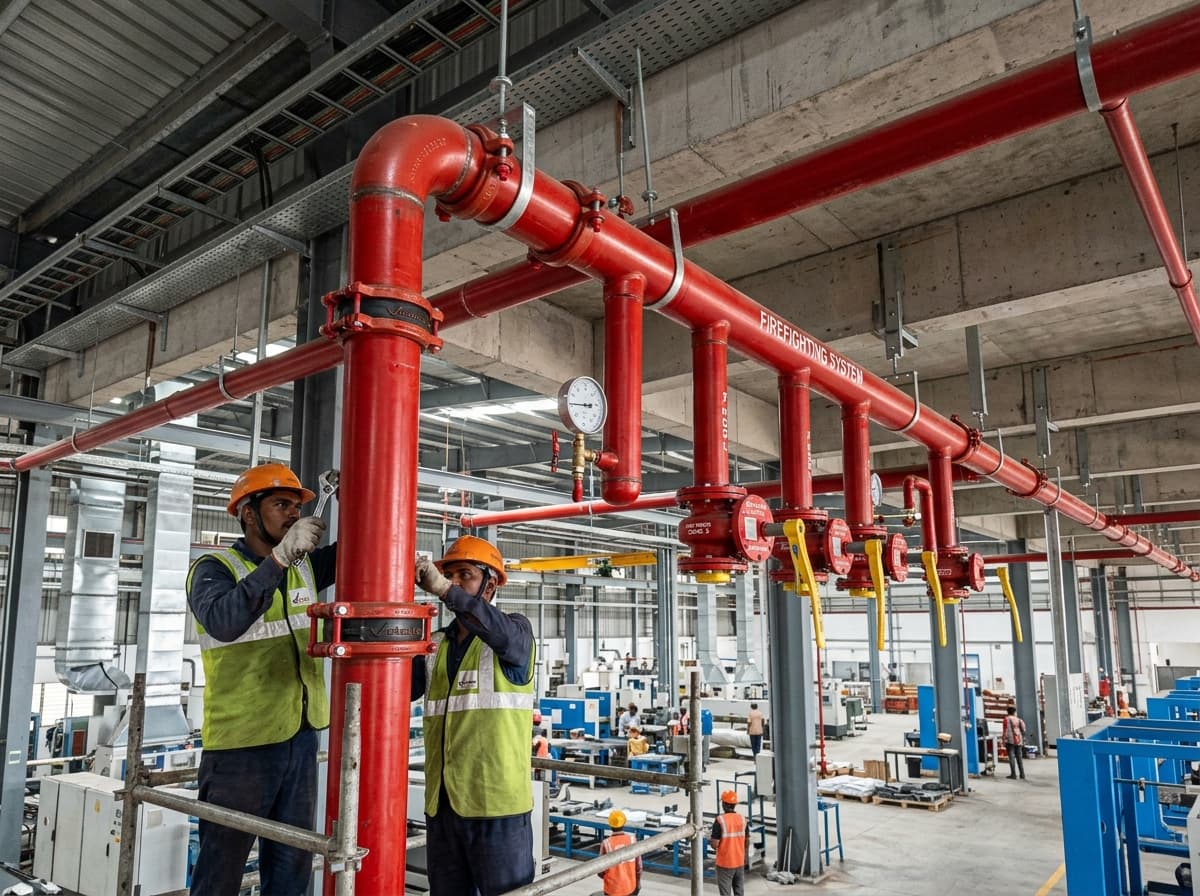
HYDRAULIC PIPING SCOPE
Heavy-class ERW distribution ring main with grooved mechanical couplings and engineered pipe supports installed across an industrial facility.IS 2190 Standard Protocol
✔Dedicated static fire water tank sizing: Minimum 100,000L to 300,000L+ reserve reserved strictly for fire protection
✔Physical isolation of domestic draw-offs: Domestic connections must terminate above the fire water reserve line
✔Split-compartment reservoir design allowing one half to be cleaned while the other maintains full fire protection
✔OS&Y rising-stem gate valves with tamper switches on all suction headers (butterfly valves prohibited on suction)
✔Anti-vortex baffle plates installed over suction sumps per IS 15301 standards
A single pump is a single point of catastrophic failure. Electrical substations and power transformers are frequently destroyed or deliberately isolated during structural fire outbreaks to prevent secondary electrocution hazards. If a facility relies exclusively on an electrically powered fire pump, its multi-crore hydrant network becomes completely inert the moment mains power trips.
NBC 2016 Part 4 and IS 15301 establish that every industrial fire pump house must incorporate an independent, tripartite pump skid:
1. Primary Electric Motor Pump: Designed for continuous S1 duty with a squirrel-cage induction motor (IP55 enclosure), horizontal split-case or end-suction centrifugal configuration delivering full rated capacity (e.g. 2,280 or 2,850 LPM at 7.0 to 10.5 Bar head).
2. 100% Standby Compression-Ignition Diesel Engine Pump: Engineered to duplicate 100% of the main electric pump capacity. The diesel engine is equipped with mechanical fuel day tanks (sized for minimum 4 to 6 hours continuous full-load run), dual 24V starting battery banks with automatic cyclic trickle chargers, and an independent mechanical speed governor.
3. Multistage Pressurization Jockey Pump: A low-flow (180 LPM), high-head vertical multistage centrifugal pump engineered to compensate for packing gland leakage, temperature expansion, and micro-losses, maintaining a steady 7.0 to 8.0 Bar line pressure without starting the 75–125 HP main pumps.
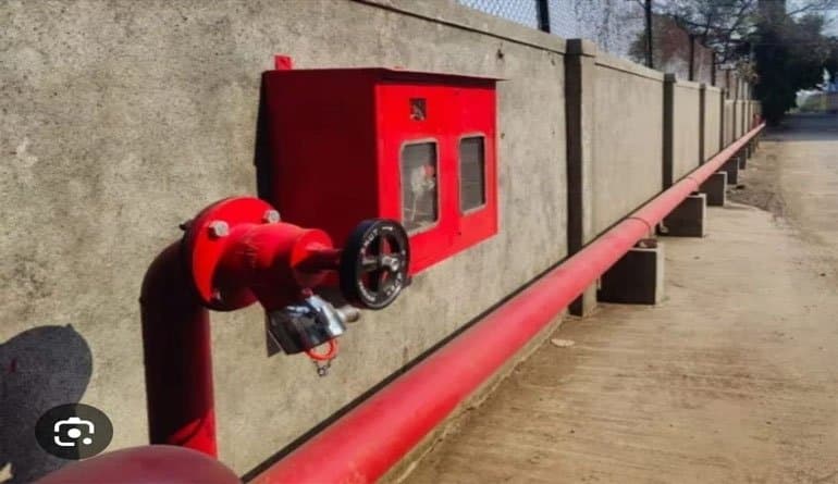
EXTERNAL YARD HYDRANT
Turnkey external yard hydrant post with stainless steel instantaneous landing valves, canvas hose cabinet, and branch pipe nozzle.IS 2190 Standard Protocol
The Staggered Pressure Switch Hierarchy & Non-Automatic Stop Rule
Pressure switches on the sensing manifold must be staggered in a fail-safe descending sequence: Jockey Pump cuts in at 7.0 Bar and cuts out at 8.0 Bar. If a hydrant opens, pressure drops further; the Main Electric Pump starts automatically at 6.0 Bar. If power is absent or pressure falls to 5.0 Bar, the Standby Diesel Pump cranks automatically. CRITICAL: Under IS 15301, both Main Electric and Diesel pumps must NEVER stop automatically upon pressure recovery; they must run continuously until manually shut down by the fire officer.
The most impeccably engineered fire pump skid is useless if it sits neglected. In industrial hubs like Bari Brahmana, Samba, and Kathua, dormant pumps frequently suffer from seized pump shafts due to hard water scale, dry-rotted mechanical packing glands, varnished diesel fuel injectors, and completely dead starter batteries.
The final pillar of the P.U.M.P. Protocol is disciplined, documented preventive testing under IS 15301 and IS 13039:
Weekly Automatic Churn Run: The main electric pump must be operated for 10 minutes, and the diesel engine pump for 30 minutes, with discharge valves closed (zero flow / churn). To prevent water inside the pump volute from boiling due to mechanical friction, a calibrated circulation relief bypass line must discharge a small, continuous stream of cooling water back into the reservoir.
Monthly Pitot Gauge Flow Proving: Opening test landing valves and measuring stream velocity with a calibrated pitot gauge to confirm rated discharge volume and verify nozzle tip pressure.
Quarterly Ring Main Flushing: Opening scour drain valves at the dead-ends of perimeter loops to flush accumulated rust scale and sediment that could otherwise choke 63mm landing valve seats or 19mm first-aid hose reel nozzles.
Annual Hydrostatic Shell Testing: Pressurizing the entire pipeline network to 1.5 times maximum pump shutoff pressure (minimum 14.0 to 16.0 Bar) for 2 hours to confirm zero drop in pressure and absolute pipe joint integrity.
INTERNAL WET RISER
Internal wet riser landing station featuring gunmetal landing valve, automatic pressure gauge, and heavy-duty swinging first-aid hose reel drum.IS 2190 Standard Protocol
Selection of pump room capacity, static water tank volume, and distribution pipe sizing is legally governed by the National Building Code (NBC 2016 Part 4 Table 7) based on building occupancy, floor area, and fire hazard classification. Below is the statutory engineering specification matrix enforced across J&K industrial corridors:
Hazard Classification
Building Type & Occupancy
Min. Static Water Tank
Main Pump Discharge
Ring Main Header
Light Hazard
Offices, Educational & Small Commercial (<15m)
50,000 to 100,000 Liters
1,620 LPM (450 GPM) @ 5.6 Bar
100mm NB (4 Inch) Class C
Ordinary Hazard (Group 1)
Hotels, Hospitals, Assembly Complexes (>15m)
100,000 to 150,000 Liters
2,280 LPM (600 GPM) @ 7.0 Bar
150mm NB (6 Inch) Class C
Ordinary Hazard (Group 2)
Pharma Formulation, Packaging, Light Engineering
150,000 to 200,000 Liters
2,280 LPM (600 GPM) @ 7.0 Bar
150mm NB (6 Inch) Class C
High Hazard (Industrial)
Chemical Processing, Solvent Storage, Distilleries
200,000 to 300,000+ Liters
2,850 LPM (750 GPM) @ 8.8 Bar
200mm NB (8 Inch) Heavy
Special High Hazard
Flammable Bulk Storage, Petroleum Warehousing
Special Hydraulic Sizing
3,800 to 5,000+ LPM Skids
200mm / 250mm NB Ring
8. Critical Engineering DOs and DON'Ts in Hydrant & Pump Skid Installation
Review these non-negotiable engineering directives derived from BSS Fire field audits and NBC 2016 commissioning standards across Jammu & Kashmir:
✓
CRITICAL DOs (Life-Saving Actions)
Immediate Emergency Protocol
✓
DO Maintain Flooded Positive SuctionPosition the fire pump room below static water tank level with eccentric flat-top-down reducers to permanently eliminate cavitation air pockets.
✓
DO Install Anti-Vortex Baffle PlatesFix heavy gauge stainless steel or epoxy-coated anti-vortex plates over suction sumps per IS 15301 Annex B to stop whirlpool air entrainment.
✓
DO Enforce Manual-Only Stop for Main PumpsWire electric and diesel fire pump controllers for automatic pressure start, but strictly manual-only stop to prevent hazardous pressure cycling.
✓
DO Provide Dual Independent Battery BanksEquip diesel fire engines with dual 24V commercial lead-acid/tubular battery banks connected to an automatic cyclic changeover trickle charger.
✓
DO Conduct Weekly Churn Runs with Bypass CoolingRun pumps for 10 to 30 minutes every week against closed valves with an open volute circulation relief bypass line to lubricate seals and clear scale.
✕
DANGEROUS DON'Ts (Fatal Errors)
Prohibited Evacuation Behaviors
✕
DON'T Use Concentric Reducers on Pump SuctionConcentric reducers create an air trap along the upper pipe wall that gets pulled into the impeller throat, triggering severe cavitation and impeller erosion.
✕
DON'T Tap Domestic Water Below Fire Reserve LineNever connect factory processing or domestic utility pipes at the bottom of the fire tank; domestic connections must pull only from surplus overflow.
✕
DON'T Install Butterfly Valves on Pump Suction LinesButterfly valve discs sit directly in the water path, causing fluid turbulence and air vortexing. Use full-bore rising-stem OS&Y gate valves with tamper switches only.
✕
DON'T Connect Ring Mains in Dead-End Tree BranchesDead-end branches suffer extreme friction head drops during simultaneous hydrant use. Always complete a closed perimeter loop with section isolating valves.
✕
DON'T Allow Pumps to Run in Churn Without CoolingRunning high-capacity centrifugal pumps at zero flow without a circulation relief line boils internal water within 10 minutes, destroying mechanical seals.
9. Field Inspection & Single-Window Fire NOC Commissioning in J&K
Achieving statutory Fire NOC approval through the Jammu & Kashmir Single Window System requires comprehensive hydraulic proof testing verified by local fire authorities. BSS Fire guides industrial and commercial clients through every commissioning milestone:
Milestone 1: As-Built Hydraulic Calculation Dossier. Preparing certified pipe schedule drawings, static and friction head calculation sheets (Hazen-Williams formula), pump characteristic curves, and underground pipe routing schematics.
Milestone 2: Pump House Skid Integration & Electrical Interlock Audit. Verifying starter panel busbars, motor overload relays, diesel engine auto-crank cycles upon power isolation, and fire alarm interlock module integration.
Milestone 3: Static Pressure Hold & Two-Stream Dynamic Residual Test. Conducting on-site physical proof tests witnessed by fire inspectors: holding 15.0 Bar hydrostatic pressure on piping, followed by opening two remote 63mm yard landing valves to prove minimum 3.5 Bar residual pressure at nozzle discharge.
Milestone 4: Form B Annual Maintenance Certification. Registering compliance documentation and establishing quarterly AMC audit protocols mandated under J&K Fire Services rules.
Need Fire NOC Approval or Hydraulic Sizing in J&K?
BSS Fire provides complete hydraulic engineering, CAD layout drafting, liaisoning, and execution for J&K Single Window Fire NOC compliance across Jammu, Bari Brahmana, Samba, Kathua, and Srinagar.
10. Turnkey Hydrant EPC & Pump Skid Engineering in J&K
Baalaay Safety Solutions (BSS Fire) is Jammu & Kashmir's premier fire protection engineering contractor, with over 25 years of field expertise delivering turnkey hydraulic fire fighting systems across the state's primary industrial hubs.
From initial hazard classification and CAD pipeline routing to pump skid fabrication, heavy ERW pipe grooving, hydrostatic proof testing, and statutory Fire NOC certification, our engineering team executes projects with zero compromise on quality or compliance.
Whether you are setting up a new pharmaceutical formulation unit in Samba IGC, modernizing an industrial pump house in Bari Brahmana, or engineering wet riser infrastructure for a commercial hotel in Jammu, consult with BSS Fire for certified execution capability.
Consult with BSS Fire Hydraulic Engineers in Jammu
Contact BSS Fire at +91-7006529259 or email bssfirejammu@gmail.com to schedule an on-site facility survey, BOQ sizing, or pump room rehabilitation audit in Jammu & Kashmir.
Engineered Execution & Supply
Need Turnkey Fire Hydrant Systems & Pump Room Installation for Your Facility?
Consult directly with Jammu-based fire protection contractors for on-site survey and BOQ sizing.
What is the minimum pressure required at a fire hydrant landing valve under Indian standards?
Under IS 13039:2014 and NBC 2016 Part 4 Table 7, a fire hydrant system must maintain a minimum dynamic running pressure of 3.5 Bar (35 meters of head) at the hydraulically most remote and disadvantaged landing valve, with at least two standard 63mm hydrant streams operating simultaneously. Maximum static pressure must not exceed 7.0 Bar to prevent dangerous nozzle reaction force on operating personnel.
Why is positive flooded suction mandatory for fire pumps under IS 15301?
Under IS 15301 Clause 5, positive flooded suction ensures that the centerline of the pump suction inlet sits below the lowest effective water level of the static reserve tank. Positive suction eliminates the risk of lost prime, foot valve failure, or suction line air leaks. Negative suction (suction lift) is strictly prohibited for industrial fire installations because a fire pump must be capable of instantaneous discharge without manual priming.
What is the difference between an eccentric and concentric reducer on fire pump suction?
A concentric reducer slopes symmetrically on both sides, creating a high-point cavity along the top of the pipe where pocketed air accumulates. This trapped air is drawn into the pump eye, causing severe cavitation and impeller erosion. An eccentric reducer installed flat-top-down maintains a completely flat upper horizontal surface, allowing fluid to flow without air pocket formation and ensuring smooth, cavitation-free intake.
Why are fire pumps wired for manual-only shutdown instead of automatic stop?
Under NBC 2016 and IS 15301, primary electric and standby diesel fire pumps must start automatically via pressure switches upon a pressure drop, but must NEVER shut down automatically when pressure recovers. In a real firefighting operation, nozzles are opened and closed intermittently by firefighters. If pumps shut down automatically whenever line pressure briefly spiked, the motors and engines would cycle rapidly, tripping overload circuits or causing engine starter burnout during the height of an emergency.
How often should industrial fire pumps undergo churn testing?
Under IS 15301 and NBC maintenance standards, fire pumps must undergo weekly churn testing. The electric motor pump should run for 10 minutes and the diesel engine pump for 30 minutes against closed discharge valves. The pump volute must be equipped with an automatic casing relief bypass valve to circulate cooling water back to the suction tank to prevent water boiling inside the pump casing.